
Interface hierarchy described in the G.703 standard allows transmission of a number of 64 kbps channels. Base 64 kbps channel may be used to transmit one uncompressed phone call and may be also used to transfer other digital information.
G.703 interfaces exist in some of our product like G.703 routers and G.703 converters.
Speaking of G.703, other standards like G.704 and G.706 should also be mentioned. The G.703 standard describes only electrical parameters of the interfaces (voltage levels, pulse shapes, line coding, etc.). The G.704 describes the division of the stream into so-called timeslots - 64 kbps channels. The G.706 defines rules of achieving synchronization between two devices and methods of computing and transmitting CRC4 checksum.
Throughputs
The G.703/G.704 standards define following data streams:
- 64 kbps
- 1544 kbps (24 channels 64 kbps each, used in the USA, called T1)
- 2048 kbps (30 channels 64 kbps each, used in Europe, called E1)
- 6312 kbps (4 concatenated 1544 kbps streams, T2)
- 8448 kbps (4 concatenated 2048 kbps streams, E2)
- 32 064 kbps (5 streams 6312 kbps each, used in Japan)
- 34 368 kbps (4 streams 8448 kbps each, E3)
- 44 736 kbps (7 streams 6312 kbps each, T3)
- 97 728 kbps (3 streams 32 064 kbps each)
- 139 264 kbps (4 streams 34 368 kbps each, E4)
The sum of component subchannels is smaller than the whole channel (e.g. 4 * 2048 kbps = 8192 kbps, not 8448 kbps) - the remaining part of the stream is used for synchronization or transmitting alarms and checksums.
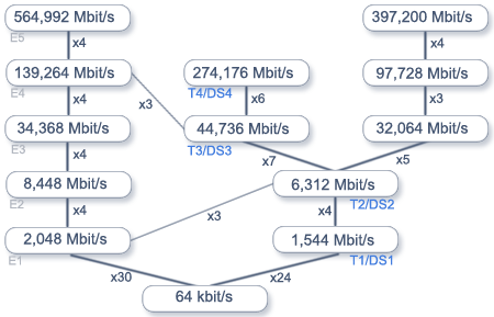
Fig. 1 PDH hierarchy
On the picture above you can see dependencies between various streams. Higher throughputs described in other standards were also included.
The term 'plesiochronous' means 'almost synchronous'. 'Almost' because there's no ideal clocking sychronization of all devices, thus there may be subtle differences of subsequent link frequencies. Multiplexing techniques used allow so-called bit stuffing - inserting and dropping of additional bits, which compensate bitrate differences. These bits are removed during demultiplexing.
Bits encoding
The basic coding scheme is AMI (Alternate Mark Inversion). Zero is coded as zero, one as a +1 or -1 pulse lasting for 50% of the bit and zero lasting for the remaining 50%.
To prevent inserting of the DC component, ones are coded alternatively - first as +1, then as -1 and so on. Sometimes this rule may be violated (+1 sent after +1 or -1 after -1) to introduce other codings described below.
Thanks to the encoding of ones such signal may be used to synchronize receiver's clocking. Unfortunately in a stream consisting only of zeros there are no pulses allowing synchronization. Therefore new coding schemes were introduced, where sequences of zeros were appropriately modified:
- B3ZS (HDB2 - High Density Bipolar 2) - each sequence of 3 zeros is replaced by 00V or B0V, where 'B' means an pulse conforming to AMI (as if there was an one in this position), and 'V' - AMI rule violation described above. Choice between 00V and B0V is done to ensure an odd number of B pulses between subsequent V pulses. In other words - subsequent V pulses must have different polarization to prevent inserting of DC component.
- HDB3 - similar to HDB2, each sequence of 4 zeros is replaced by 000V or B00V.
- B6ZS - sequence of 6 zeros is replaced by 0VB0VB
- B8ZS - sequence of 8 zeros is replaced by 000VB0VB
The HDB3 coding is used at 2048 kbps, 8448 kbps and 34 368 kbps.
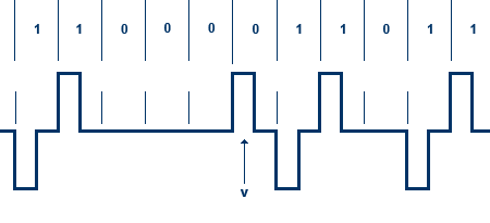
Fig. 2 HDB coding
Framing
The framing method is different for each throughput, so we will focus on 2048 kbps framing - like one used in Tahoe devices.
One frame consists of 256 bits numbered from 1 to 256. Frames are sent with frequency of 8000 Hz, which gives a total throughput of 2048000 bits per second. Each 8 subsequent bits of a frame form so-called timeslot. If each timeslot occupies 8 bits of each frame and frames are sent 8000 times per second, then one timeslot has throughput of 64 kbps.
First 8 bits (timeslot 0) is used for synchronization. These bits take alternating functions in subsequent frames:
| Bit: | 1 | 2 | 3 | 4 | 5 | 6 | 7 | 8 |
|---|---|---|---|---|---|---|---|---|
| Frame containing FAS (Frame Alignment Signal) | Si | 0 | 0 | 1 | 1 | 0 | 1 | 1 |
| Frame without FAS | Si | 1 | A | Sa4 | Sa5 | Sa6 | Sa7 | Sa8 |
Si - bit for international use (e.g. CRC4 checksum)
A - alarm information
Sa4-Sa8 - spare bits, may be used for other purposes
Apart from timeslot 0 used for synchronization, timeslot 16 is used for signaling - e.g. transmitting an information about incoming phone call in one of the channels.
The signaling is sent in 16 subsequent frames. In the first one, in the 16th timeslot there are only spare bits. In each of the following frames there are 4 bits for two channels (8 bits in all - a whole timeslot). So 15 frames contain signaling for all the 30 free timeslots (from 1 to 15 and from 17 to 31).
| Timeslot 16 of frame 0 | Timeslot 16 of frame 1 | Timeslot 16 of frame 2 | ... | Timeslot 16 of frame 15 | ||||
|---|---|---|---|---|---|---|---|---|
| 0000xyxx | abcd channel 1 | abcd channel 16 | abcd channel 2 | abcd channel 17 | ... | abcd channel15 | abcd channel 30 | |
- Channel numbers indicate phone channels. Channels from 1 to 30 are assigned to, respectively, timeslots from 1 to 15 and 17 to 31.
- a, b, c and d mean 4 signaling channels, 500 bps each.
- x - unused bits
- y - alarm information
CRC4
The Si bit may be used to transfer the CRC4 checksum. The four-bit checksum is transmitted in Si bits of eight subsequent frames. It is computed from 2048 bits of data sent in 8 previous frames. Such eight frame sequence is called a sub-multiframe (SMF). Every second SMF contains additional bits used to signal errors detected during the transmission. A sequence of two SMFs makes a full multiframe.
| Sub- multframe | Frame number | Frame bits | ||||||||
| 1 | 2 | 3 | 4 | 5 | 6 | 7 | 8 | |||
| M u l t i f r a m e | 1 | C1 | 0 | 0 | 1 | 1 | 0 | 1 | 1 | |
| 2 | 0 | 1 | A | Sa4 | Sa5 | Sa6 | Sa7 | Sa8 | ||
| 3 | C2 | 0 | 0 | 1 | 1 | 0 | 1 | 1 | ||
| I | 4 | 0 | 1 | A | Sa4 | Sa5 | Sa6 | Sa7 | Sa8 | |
| 5 | C3 | 0 | 0 | 1 | 1 | 0 | 1 | 1 | ||
| 6 | 1 | 1 | A | Sa4 | Sa5 | Sa6 | Sa7 | Sa8 | ||
| 7 | C4 | 0 | 0 | 1 | 1 | 0 | 1 | 1 | ||
| 8 | 0 | 1 | A | Sa4 | Sa5 | Sa6 | Sa7 | Sa8 | ||
| 9 | C1 | 0 | 0 | 1 | 1 | 0 | 1 | 1 | ||
| 10 | 1 | 1 | A | Sa4 | Sa5 | Sa6 | Sa7 | Sa8 | ||
| 11 | C2 | 0 | 0 | 1 | 1 | 0 | 1 | 1 | ||
| II | 12 | 1 | 1 | A | Sa4 | Sa5 | Sa6 | Sa7 | Sa8 | |
| 13 | C3 | 0 | 0 | 1 | 1 | 0 | 1 | 1 | ||
| 14 | E | 1 | A | Sa4 | Sa5 | Sa6 | Sa7 | Sa8 | ||
| 15 | C4 | 0 | 0 | 1 | 1 | 0 | 1 | 1 | ||
| 16 | E | 1 | A | Sa4 | Sa5 | Sa6 | Sa7 | Sa8 | ||
C1-C4 - CRC4 checksum bits
E - CRC4 error signaling
Sa4-Sa8 - unused
A - alarm information