

|
Tahoe Products - Efficient and Reliable Below you will find information on our products: |
||
 |
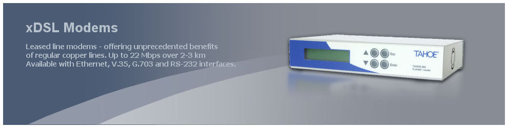
xDSL ModemsLeased line modems - ahead with revolutionary G.shdsl+ modems offering unprecedented benefits of regular copper lines. Up to 20 Mbps over 2-3 km! Available with Ethernet, V.35, G.703 and RS-232 interfaces. |
|
|
|
||
 |
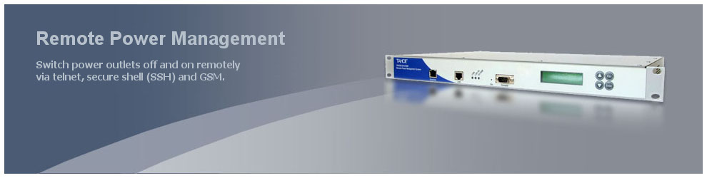
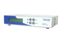
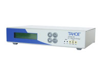
Remote Power ManagementShorten unavailability periods of your network by switching power outlets off and on remotely and monitoring power supply. Accessible via telnet, secure shell (SSH), SNMP, web and GSM. |
|
|
|
||
 |
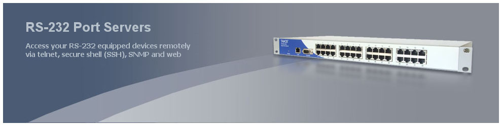
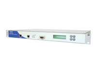
RS-232 Port ServersAccess your RS-232 equipped devices remotely via telnet, secure shell (SSH), SNMP and web. |
|
|
|
||
 |
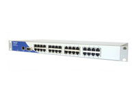
V.35/Ethernet WAN Routers (with Frame Relay, PPP and Cisco HDLC support)Access the Frame Relay network or connect two LANs using a leased line terminated with V.35 interfaces. |
|
|
|
||
|
G.703 (E1)/Ethernet WAN Routers (with Frame Relay, PPP and Cisco HDLC support)Use of G.703 streams never was that easy - connect LAN on one side and E1 line on the other. |
|
|
|
||
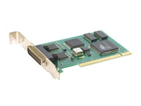 |
WAN PCI cards (V.35, G.703/E1)Synchronous cards add the functionality of a WAN router to the regular PC working under control of Linux or FreeBSD operating systems. |
|
|
|
||
 |
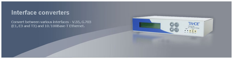
Interface converters & bridgesConvert between various interfaces - V.35, G.703 (E1, E3 and T3) and 10/100Base-T Ethernet. |
|
